Cart (1)
Close
-

CANbridge NT 200 - 2 Channel
Qty: 1 $418.00
Subtotal: $418.00

$2,830.67
![]()
CANObserver
For machines with CANBus network to work optionally the whole control system needs monitoring continually. With age and wear and tear, bus system components will show progressive deterioration of running parameters. These changes can be monitored, diagnosed and reported using GEMAC CANObserver and can be notified to the maintenance manager.
To know more about this product check the youtube link.
This product will take upto 5 weeks for delivery.
![]()
If the system stands still, the loss is usually high.
To perform some corrective action at the right time, system components and the whole guidance system should be maintained continual. Because of wear there are worsening of running parameters of the bus system. These changes are diagnosed from our CANobserver within the running system and are notified to the facility operator.
Bus Systems
The CANobserver works within the networks CAN, CANopen, DeviceNet und SAE J1939.
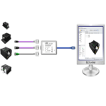
Installation and Configuration
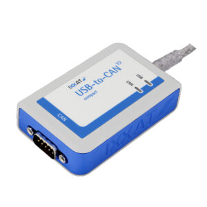
The CANobserver is designed to be permanent mounted into the bus. The top-hat rail makes it easy to install. It can use the bus power supply (9…36 V), additionally you need a Ethernet connection to connect.
Configuration is done in the web browser completely. Check if the alarm threshold fit to your system and put in the data for email sending.
Output Switch
On which problems you want to be warned, you define with your web browser. The following screenshot shows an example.
With the potential free switch you can switch a signaling lamp on top of your control cabinet for instance.
Additionally you can be warned via E-Mail and SMNP. Therefore an online connection to the ethernet network is needed.
Measurements
The CANobserver is capable to measure and to show signal conditions of the CAN bus. It is possible to draw conclusions to perhaps existing problems about the nodes or the bus wiring by measurements of signal quality.
Active-Error /Passive-Error Frames
Overload Frames
Acknowledge Errors
General Quality Level (0 … 100 %)
Disturbance-free Voltage Range
Edge Steepness (worst falling and rising edges)
Additionally to the logical and physical measurements the CANobserver is getting data about bus status, bus traffic load and the optional CAN supply voltage.
Certifications
The CANobserver fits into the definitions of VDI/VDE guideline 2184. (Preview)
CE conformity
Device Safety : EN 60950 – 1 : 2003-03
EMC
• low-frequence electromagnetic interference : EN 61000 – 3-2 : 2000, +A1 : 2001, +A2 : 2004
• high-frequence electromagnetic interference : EN 55022 : 1998, +A1:2000, +A2:2003
• immunity : EN 61000 – 6-2 : 2001
$2,830.67


