Cart (1)
Close
Subtotal: $684.20
Subtotal: $684.20

Subtotal: $684.20

$8,033.52
![]()
Possibilities
The CAN-Bus Tester 2 is a widely used measuring device for control of bus parameters. The success story starts already in year 2002 with the first model. The hardware was completely redesigned in version 2. The corresponding software is still developed and has been enhanced with extensive updates.
Check the setup of the bus before you switch on with the bus wiring test, measure under running conditions down on the physical layer and analyses data of the nodes with the protocol monitor. The long time monitor shows scattered errors and creeping signal loss.
The trigger output makes it possible to show data of only one node of the bus.
The great box contents within the service case with big adapter set makes it possible to use the device out of the box in many environments. You can safe your measurements and print a status protocol directly from the software.
Bus Systems
The measuring device works in the networks CAN, CANopen, DeviceNet and SAE J1939.
To know more about this product check the youtube link.
This product will take upto 5 weeks for delivery.
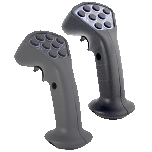
66GEMAC CAN-Bus Tester 2
Possibilities
The CAN-Bus Tester 2 is a widely used measuring device for control of bus parameters. The success story starts already in year 2002 with the first model. The hardware was completely redesigned in version 2. The corresponding software is still developed and has been enhanced with extensive updates.
Check the setup of the bus before you switch on with the bus wiring test, measure under running conditions down on the physical layer and analyses data of the nodes with the protocol monitor. The long time monitor shows scattered errors and creeping signal loss.
The trigger output makes it possible to show data of only one node of the bus.
The great box contents within the service case with big adapter set makes it possible to use the device out of the box in many environments. You can safe your measurements and print a status protocol directly from the software.
Bus Systems
The measuring device works in the networks CAN, CANopen, DeviceNet and SAE J1939.
The CBT2 can also be used for measurements in other bus systems based on the CAN standard. These include Isobus, NMEA 2000 and SafetyBus P, but also Energybus, CANaerospace and ARINC825. Niche bus systems are MilCAN and CANopen Lift.
Licence Model
In the basic configuration the CAN-Bus Tester 2 is enabled for bus system CAN. You can do all physical measurements within this system.
Additional licenses are offered to the systems CANopen, DeviceNet and SAE J1939. With them it is much easier to assign the messages to the real nodes.
The optional protocol monitor is for logical bus analysis in the bus systems CAN (transmit /receive), CANopen (receive) and SAE J1939 (receive).
The user software is free to download and use, only for measurements with the CAN-Bus Tester 2 it has to be unlocked.
Connections
Power Supply
The device works with 9 – 36 V. Only for the Bus Wiring test min. 24 V are needed.
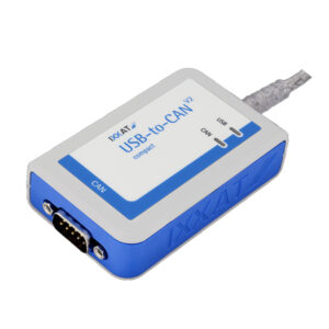
USB Port
Connect your windows PC or laptop here.
CAN and CAN probe port
Two 9-pin D-Sub ports are for connection to the bus and for probes
Trigger Output
For further measurements with a digital storage oscilloscope the CAN-Bus Tester 2 can be used as trigger source.
Two Devices in one
The CAN-Bus Tester 2 is basically a 2-in-1 device. One part is responsible for the extensive measurements on the physical level. 64-fold sampling of each individual bit makes detailed evaluation possible.
The other part is a CAN-to-USB interface for comprehensive protocol analysis. Both parts of the device can work independently of each other or simultaneously and together.
Among many other things, it is possible to stop the protocol analysis automatically if the physical measuring device has detected a problem. In this way, the data traffic can be evaluated immediately before an error occurs. You don’t have to search through long lists of telegrams, the end of the list is the relevant point.
Bus Wiring Test
With the wiring test, it is possible to determine line short-circuits, line breaks, the bus termination, the loop resistances of the CAN line and the CAN power supply line, and the overall line length.
To ensure correct bus cabling, it is recommended to perform the wiring test at the beginning of any plant measurements.
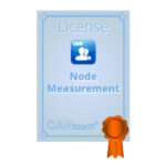
Node Measurement
Connect the CAN-Bus Tester 2 to your bus line. Your should see a green led on your display, showing that there is data traffic.
First start the baud rate scan, then scan for nodes. All messages on the bus are now received and analysed, the nodes with their ID are listed. Name the nodes if you want for better overview.
With the measurement “all stations view” you get an overview of the quality levels of the signals. The bar diagram makes it ease to compare. At continuous mode you will additional see the min/max values. You can easily compare to a saved measurement.
The measurement “one stations view” shows the single values of one node and shows a physical and logical decoded oscillogram. Quality level, edge steepness and disturbance free voltage range are the three showed measurands. By starting a continuous measurement you will also see min/max of quality level and the variation of the disturbance-free voltage range.
Online Monitor
This measurement runs continuously and compares with given thresholds. If it overruns the threshold the error will be registered. At single measurement mode it stops and the faulty message is showed in the oscilloscope view. In continuous mode the error is marked in a time diagram. So you show when your threshold was overrun’ed or if a errorframe has occurred.
The observed values are
Active-Error /Passive-Error Frames
Overload Frames
Acknowledge Error
General quality level (0 … 100 %)
Disturbance-free voltage range (minimum noise free differential voltage)
Edge steepness (worst rising and falling edge of a message)
Additionally to this logical and physical measurements the CAN-Bus Tester 2 is continuously determining bus traffic load, bus status and the optional CAN supply voltage.
The software can be adjusted in a way, that a simultaneously running Receive in the protocol monitor is stopped in case of an error. So it is easier to analyse that data traffic that was on the bus before the error occurred.
Protocol Monitor
Many features of the CANvision Protocol Monitor are build in the CAN-Bus Tester 2 user software. It is easily unlocked when you buy a license.
Inform yourself about the range of features of CANvison here.
Main difference is the network capability, this can only be used with the full version of CANvision.
$8,033.52


